today I tell about tube light.It's very good jobs.You can do this.So learn step by step.Please like us and leave a comments.also read well.you should be visit everyday because our blog is daily update.
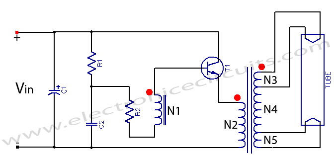
Fluorescent Tube Light Circuit
of an inverter that uses a single transistor and a single transformer.
This type inverter can be made in various ratings such as 6V, 10 Watts;
6V, 20Watts; 12V, 20Watts etc. Details of a few types are given below:

| Fluorescent Tube Light Circuit PARTS LIST | |||
| 6V, 10Watts Design | 6V, 20Watts Design | 12,V 20 Watts Design | |
| Vin | 6V DC | 6V DC | 12V DC |
| R1 | 680Ω, 2W | 330Ω, 3W | 150Ω, 5W |
| R2 | 3.3Ω, 0.5W | 2.2Ω, 0.5W | 5.6Ω, 0.5W |
| C1 | 100µF, 16V | 100µF, 16V | 10µF, 25V |
| C2 | 0.47µF, 16V | 0.47µF, 16V | 0.33µF, 30V |
| T1 | 2N3055 | ||
| X1 | Pot core 26/16, 10W | Pot core 26/16, 20W | Pot core 26/16, 12V, 20W |
| N1 | 16T, 30SWG | 18T, 30SWG | 30T, 34SWG |
| N2 | 10T, 20SWG | 10T, 20SWG | 20T, 24SWG |
| N3 | 3T, 30SWG | 5T, 32SWG | 6T ,36SWG |
| N4 | 85T, 30SWG | 112T, 32SWG | 191T, 36SWG |
| N5 | 2T, 30SWG | 3T, 32SWG | 3T, 36SWG |
| TUBE | Fluorescent tube light 10W | Fluorescent tube light 20W | Fluorescent tube light 20W |
Notes:
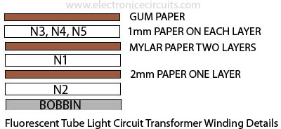
1. N3, N4, N5 continuous winding
2. The dot in the circuit indicates start of winding.


